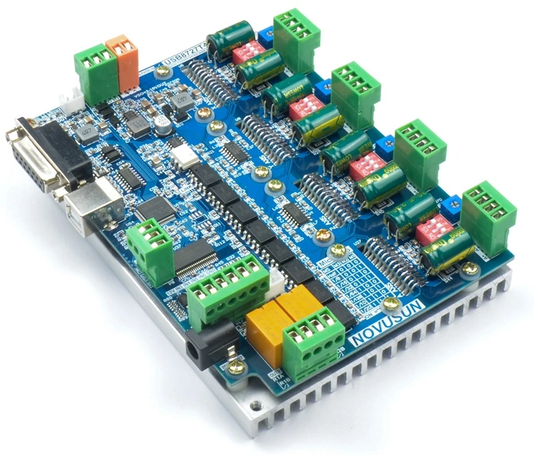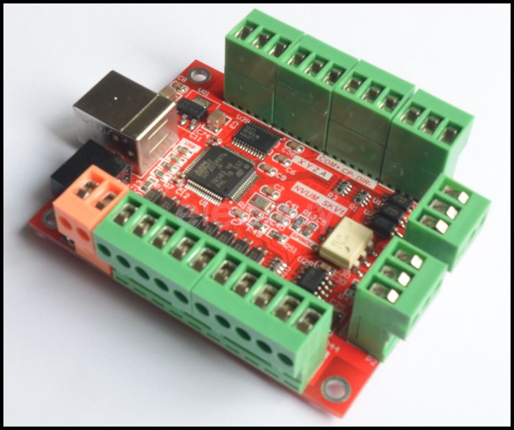

I assume you are using a Chinese 6040 X,Y,Z and A (rotary) 4 axis setup. The settings they have posted have worked for me but you need to also look at settings for 'direction, homing, axis calibration' and so on to get your machine into working order. Secondly, Follow the suggestions posted by Tweaky and Claudio.

Without this, you cannot run more than about 50 lines of g.code. I understand that Mach3 is no longer being 'developed' (read: making it work for ordinary users) so I can offer you a couple of suggestions to see if they are of help.įirstly, you need to be sure you have a license loaded into the Mach3 folder on your computer's drive. You will probably find that the Bitsensor board is okay anyway but there are other boards for sale which are reasonably cheap and even more refined. is concerned, the problem I have had for some time has been the 'try before you buy' limitations of the Mach3 software. Yes, my setup is running well (at last) as far as driving the motors, etc. This method should prevent a single failure from destroying everything. If you want everything grounded together (and you should), run a separate ground wire from each piece of equipment to a common grounding point near your master power input. Each serves an isolated purpose, and their isolation is an attempt to protect your equipment.

Note: DCM, ACM, and GND (all grounds) are not connected together. Choosing the right method may require some experimentation. Note: For the motor drivers, you will use either the 5V or the GND connection, not both. This should come from the VFD low voltage supply (10V to 13V) output.Ħ) 5V: is a low power output to supply the motor driver opto-isolators providing you use "Low-True" logic (pull to ground for ON)ħ) GND: output is the ground to the motor drivers used when driving "High-True" logic (Pull to 3,3V to 5V for ON). It goes to the AVI pin on the VFD.ĥ) 10V: is the input analog reference voltage for the spindle speed control. It goes to the ACM pin on the VFD.Ĥ) AVI: is the analog output to the spindle speed control. It is usually the same voltage that supplies the motor drivers, but it can be a separate supply (200ma minimum).Ģ) DCM: connection is digital ground for both input switches (Limits, E-Stop, & Probe) and output loads (VFD Start, Flood, & Mist).ģ) ACM is the analog ground specifically for the spindle speed control. To add a little more to the BSMCEO4U-PP definitions.ġ) 24V: Input can be anywhere from 12V to 36V to power the digital input and outputs only.


 0 kommentar(er)
